|
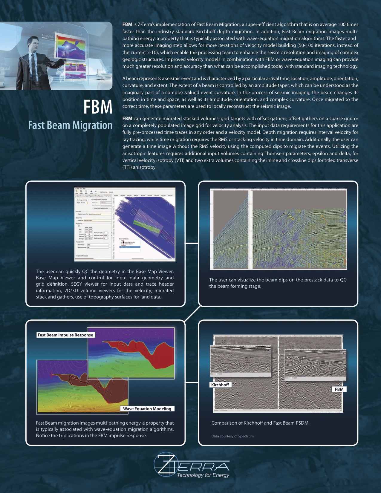
FBM is Z-Terra’s Fast Beam Migration, a super-efficient algorithm that is two orders of magnitude faster than the industry standard Kirchhoff depth migration. Fast Beam Migration images multipathing energy, a property that is typically associated with wave equation migration algorithms. The faster and more accurate imaging step allows for more iterations of velocity model building (50–100 iterations in lieu of the current 5–10.) A greater number of velocity updates enables the processing team to enhance the resolution and imaging of complex geologic structures. Improved velocity models in combination with FBM or wave equation imaging can provide much greater resolution and accuracy than that which can currently be obtained with standard imaging technology.
A beam represents a seismic event and is characterized by a particular arrival time, location, amplitude, orientation, curvature, and extent. The extent of a beam is controlled by an amplitude taper, which can be understood as the imaginary part of a complex valued event curvature. In the process of seismic imaging, the beam changes its position in time and space, as well as its amplitude, orientation, and complex curvature. Once migrated to the correct time, these parameters are used to locally reconstruct the seismic image. |
 |
| FBM can generate migrated stacked volumes, grid targets with offset gathers, and offset gathers on a sparse grid or on a completely populated image grid for velocity analysis. The input data requirements are fully preprocessed time traces in any order and a velocity model. Depth migration requires an interval velocity model in depth for ray tracing, while time migration requires an RMS or stacking velocity in time. Additionally, the user can generate a time image without the RMS velocity using the computed dips to migrate the events. Utilizing the anisotropic features requires additional input volumes containing the Thomsen weak anisotropy parameters epsilon and delta for both VTI and TTI anisotropy and two additional volumes containing the dips of the local axis of symmetry for TTI anisotropy. |  |
|
Intuitive Graphical User Interface
- Base map viewer for input data and grid definition
- Base Map to visualize beam, image, and velocity model geometry
- SEG Y viewer for input data QC and trace and header investigation
- Data viewer for 2-D and 3-D velocity models, gathers, and images
- Beam and ray QC and visualization tools
Beam Forming
- 5-D Beam Forming via plane-wave destructor filters
- Slant Stack 5-D Beam Forming
- 5-D multiple dips detection
- Anti-aliased prestack dip estimation
- Unstructured input data
- Topography corrected dips
- Input data filtering for dip estimation
Migration
- Depth migration
- Time migration without velocity
- Time migration with RMS velocity
- Automatic RMS velocity estimation
- Isotropic and anisotropic migration (VTI and TTI)
- Selective migration: migrate only the strongest or most coherent events
- Multipath energy imaging
- Quadratic travel-time approximation
- Adaptive time stepping algorithm
- Topography
Imaging
- Stacked image and offset image gathers
- Wave propagation consistent phase rotation
- Amplitude corrections
- Targets and target lines
Parallelization
- Optimization of data distribution on parallel nodes
- Input data indexing
- Job monitoring
- Node addition and removal during runtime
- Checkpoint restart
- Adaptive runtime parameter optimization
- 64-bit, for x64-86 architecture processors (also known as x64, x64_86, AMD64, EMT64T, Intel 64)
- Red Hat® Enterprise Linux® (or compatible) 4.8 and above, 5.3 and above, 6.0 and above