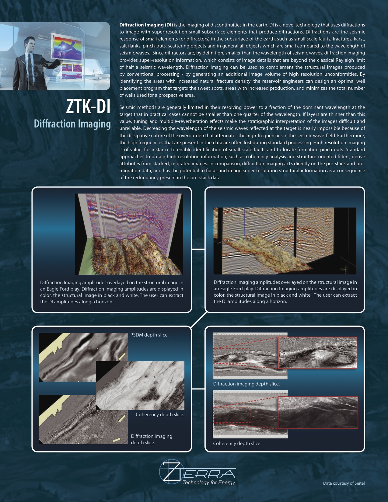
| Diffraction Imaging (DI) is a novel seismic imaging technique for focusing diffractions in order to produce super-resolution images of diffractors unattainable by conventional means. Seismic diffractors are small scale scattering subsurface elements such as small faults, fault edges, pinch-outs, salt flanks, reef or channel edges, fractures, fluid fronts, caves, karsts, subtle stratigraphic variations and discontinuities, or in general any reflector unconformities whose spatial extent is less than the seismic wavelength.Recall that the Rayleigh criterion characterizes the dependence of the resolution limit for a diffraction-limited imaging process on the wavelength and the geometry of the aperture used in that imaging process — in the seismic context these processes are limited to a fraction of the seismic wavelength that in practical cases cannot be smaller than one quarter. In order to achieve a fundamental advance in the high resolution 3-D prestack imaging of complex geological structures, Diffraction Imaging sidesteps this fundamental physical limit by conceptually upending the methodology of conventional depth imaging: whereas conventional depth imaging seeks to enhance specular reflections, Diffraction Imaging seeks to attenuate them. That is, rather than allow resolution to remain constrained by a diffraction-limited specular imaging process, this paradigm shift in methodology attempts to eliminate the contribution from specular reflectors entirely and instead enhances and focuses deviations from an ideal specular image caused by abberations in specular reflectors in order to image the small structural elements responsible for those deviations. | 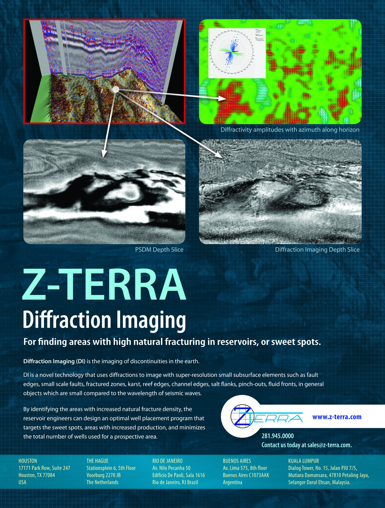 |
| Diffraction images are intended to be provided as a complementary tool to interpreters (alongside a high-quality standard reflecitvity PSDM image and its associated anisotropic velocity model) to identify areas with increased natural fracture density that will optimize well placement, improve production and recovery efficiency, reduce field development cost, and decrease the environmental impact of developing the field (by reducing the number of wells required to produce a reservoir).If layers are thinner than the Rayleigh limit, tuning and multiple-reverberation effects make the stratigraphic interpretation of the images difficult and unreliable. Decreasing the wavelength of the seismic waves reflected at the target is nearly impossible because of the dissipative nature of the overburden that attenuates the high-frequencies in the seismic wave-field. Furthermore, the high frequencies that are present in the data are often lost during standard processing.Other approaches to obtain high-resolution information, such as coherency analysis and structure-oriented filters, derive attributes from stacked, migrated images. In comparison, diffraction imaging acts directly on the pre-stack and pre-migration data, and has the potential to focus and image super-resolution structural information as a consequence of the redundancy present in the pre-stack data. | 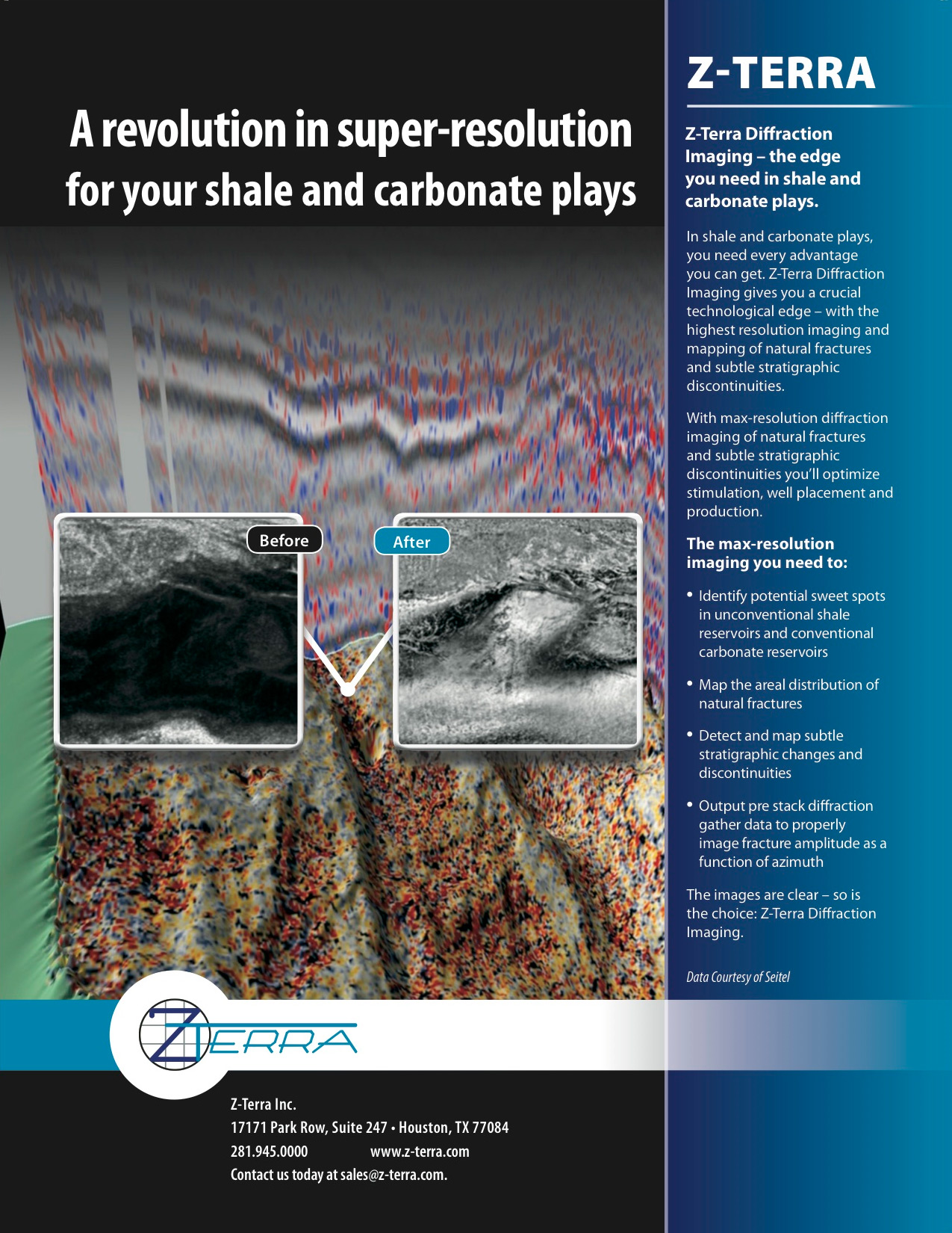 |
 |
 |
Super-Resolution Imaging
- Identify areas with increased natural fracture density.
- Applications in Eagle Ford, Bakken, Niobrara, Utica, Marcellus, Woodbine unconventional shale plays
- Identify zones of high natural fracture density in carbonates
- Applications in Middle Eastern fractured carbonates and pre-salt carbonates in offshore Brazil
- Identify and delineate karst features, small scale faults, reflector unconformities, and injectites.
Superior Illumination
- Stratigraphic terminations against salt
- Subvertical faults
- Reduced sensitivity to acquisition limits
- Differentiation between edge and tip diffractors
High Fidelity Implementation
- Time and depth implementation for PSDM and PSTM (patent pending)
- Specularity gathers generation (patent pending)
- Algorithms to detect and attenuate specular energy in specularity gathers
- Compute special attributes for enhancing diffractions
- Anti-aliasing: triangles, boxcar, multiple bandpass
- Amplitude corrections
- Aperture design
- variable aperture with depth
- Variable step with depth
- Topography
- Offset compensation
- Fold balance weighting
- Voronoi weights
- Travel-times dynamic grid
- Travel-times generation
- Most energetic travel times
- Shortest path travel times
- First arrival travel times
- Analytic travel times
- Anisotropic curved rays for PSTM
- Anisotropic VTI and TTI travel times
Efficient Cluster Implementation
- Input data stored in any order
- Optimization of data distribution on parallel nodes
- Input data indexing
- Job monitoring
- Nodes addition and removal during runtime.
- Checkpoint restart
- Adaptive runtime parameter optimization
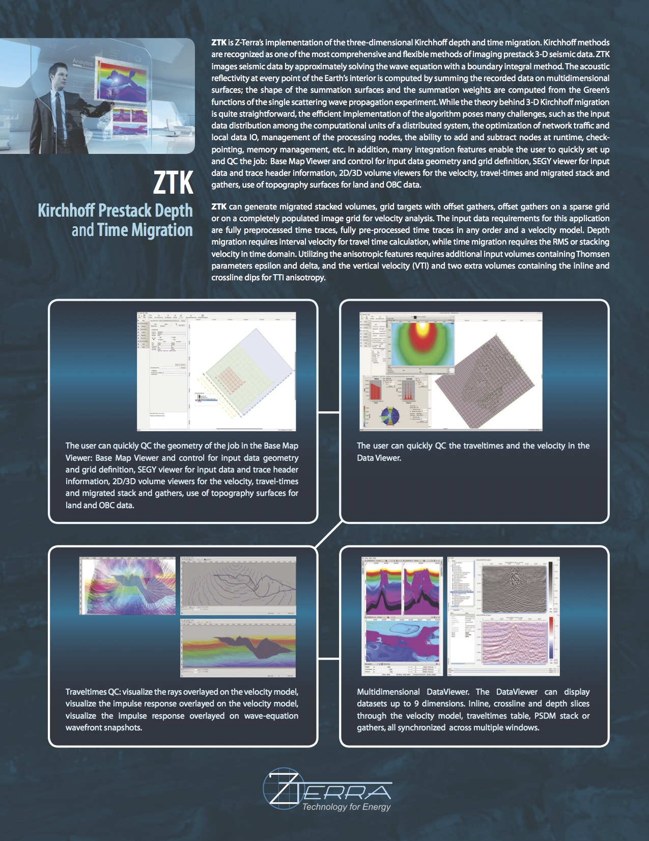
Intuitive Graphic User Interface
- Visualize data, image, travel-time, dip volume, and velocity model geometry.
- SEG Y viewer for input data QC and trace and header investigation
- Data viewer for 2-D and 3-D velocity models, travel times, gathers, and images
- Base map viewer for data and for travel-times, velocity model, and image grid definitions
- Travel-times QC and visualization tools, rays, wave-fronts
- Histrogram representation for offset and azimuth distribution
- Image mask for merged surveys
- 64-bit, for x64-86 architecture processors (also known as x64, x64_86, AMD64, EMT64T, Intel 64)
- Red Hat® Enterprise Linux® (or compatible) 4.8 and above, 5.3 and above, 6.0 and above